Brake Motors
Main features:
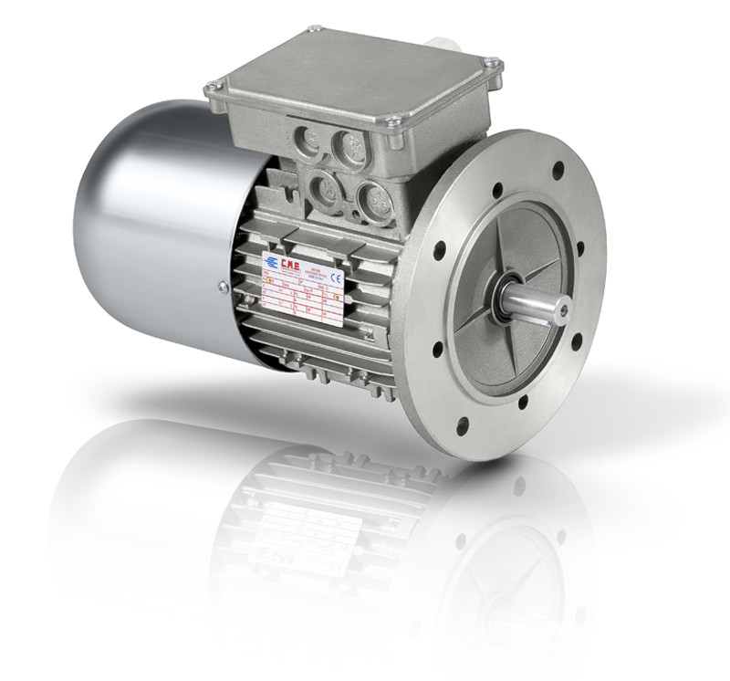
Besides standard production, C.M.E. S.r.l. also produces both single and three-phase brake motors with single or double polarity. The bodies of these brake motors are identical to standard motors’ ones, but they have a longer fan cover because, besides housing the fan, it must also protect the brake assembly.
The brake is activated when the power supply is cut off.
When the motor is running, the springs are compressed by an electromagnet powered by the line voltage. When power is cut off, springs are released and they push (with an adjustable intensity) against a cast iron or steel plate which, in turn, presses against the friction disk.
How to choose a brake motor?
The electromagnet can be operated by alternating or direct current. Normally the electrical brake connections are set in the motor terminal box, but, upon request, they can also be applied to a separate terminal box, for a separate power supply.
When choosing a brake motor, clients should take into consideration many parameters to identify the necessary braking and motor dimensions:
- The desired speed of braking
- The number of start-ups/hour
- The turning force applied to the shaft (which requires braking).
CME srl produces three types of brakes:
- “K” TYPE BRAKE (powered by direct current)
- “AC” TYPE BRAKE (powered by alternating current)
- “S” TYPE BRAKE (decelerator)
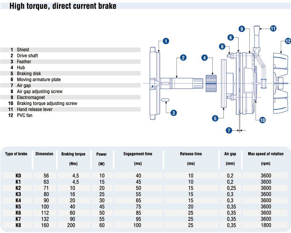
“K” TYPE BRAKE (powered by direct current)
This type of brake is normally used when more gradual, less abrupt start-up is desired. This does not affect the braking torque value, which remains the same as in the alternating current brakes.
Main features:
- Solid structure.
- Extremely silent engagement and functioning.
- Good progressive braking.
- Good heat dissipation; the fan also acts as braking disk thus helping to dissipate the heat produced during braking and therefore reducing to a minimum the wearing of friction material.
- Electromagnet’s drive coil totally submerged in epoxy resin and mechanical parts protected by a tropicalizing zinc coating.
- Upon request, a version with manual release lever can be provided.
If, however, rapid braking is required, it is possible to fit a special rectifier (Type R) which causes the armature to immediately engage the brake. It is fit with a static switch that opens the DC circuit as soon as the alternating power is cut off, thus instantly engaging the armature.
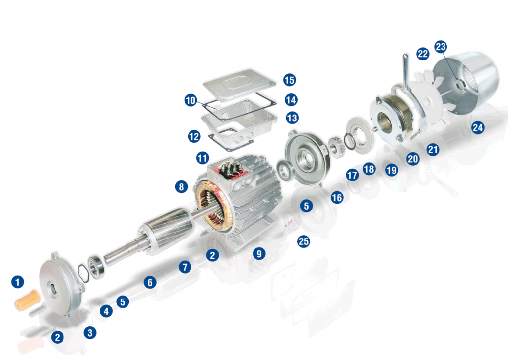
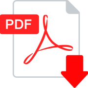
K – DC BRAKE
- 1 – Cover shaft
- 2 – Feather
- 3 – Shield
- 4 – Elastic compensation ring
- 5 – Bearing
- 6 – Drive Shaft
- 7 – Rotor
- 8 – Wound stator
- 9 – Frame
- 10 – Cable inlet
- 11 – Line connection terminal
- 12 – Cover gasket IP55
- 13 – Cover box
- 14 – Gasket IP65
- 15 – Cover box-top
- 16 – Shield brake AC-K
- 17 – Braking disk hub
- 18 – Seeger
- 19 – Breaking disk
- 20 – Magnetic “K” braking assembly
- 21 – Jan release lever (optional)
- 22 – PVC cooling fan
- 23 – Fan tightening ring
- 24 – Extended fan cover
- 25 – Motor label plate
Power is supplied through the rectifier, which draws the standard 230 Volt ± 10%, 50 Hz power from the connections in the terminal box.
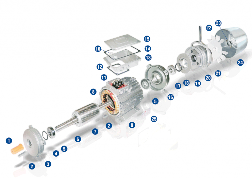
“AC” TYPE BRAKE (powered by alternating current)
This is the preferred type of brake when the motor is subject to very frequent cycles where rapid, sharp intervention is required. Moreover, it achieves braking torque values that steadily vary until they reach, and significantly exceed, 200% of the nominal torque of the motor. The prompt engagement of the armature ensures that the motor always starts up without shaft braking.
Main features:
- Solid structure
- Silent operation
- Good progressive braking.
- Good heat dissipation thanks to the conductivity of the cast aluminium body and to the motor ventilation
- Drive coil totally submerged in epoxy resin.
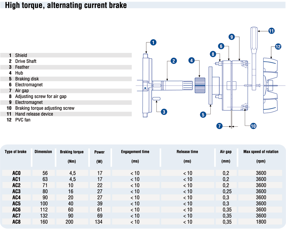
KEY AC – AC BRAKE
- 1 – Cover shaft
- 2 – Feather
- 3 – Shield
- 4 – Elastic compensation ring
- 5 – Bearing
- 6 – Drive Shaft
- 7 – Rotor
- 8 – Wound stator
- 9 – Frame
- 10 – Cable inlet
- 11 – Line connection terminal
- 12 – Cover gasket IP55
- 13 – Cover box
- 14 – Gasket IP65
- 15 – Cover box-top
- 16 – Shield brake AC-K
- 17 – Braking disk hub
- 18 – Seeger
- 19 – Breaking disk
- 20 – Magnetic “AC” braking assembly
- 21 – Jan release lever (optional)
- 22 – PVC cooling fan
- 23 – Fan tightening ring
- 24 – Extended fan cover
- 25 – Motor label plate
The power supply for standard motors is 230 / 400 Volt, 50 Hz and the power for braking is already drawn from the connection in the terminal box
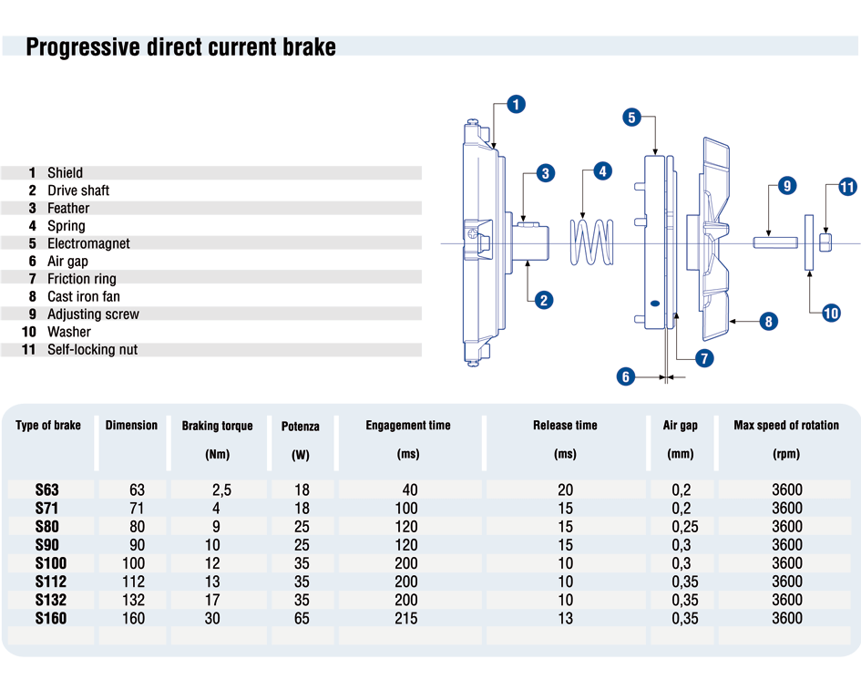
DECELERATOR (OR PARKING BRAKE) (S
His is used when delicate, gradual braking is desired, due to the cast iron fan and a significant turning weight. The friction disk, pressed by the springs when power is cut off, rubs against the back of this fan, which thus acts as braking disk too. We use a DC brake which, in three-phase motors, is powered by a rectifier connected to the terminal box between the line phase and the star point.
Main features:
- Solid structure
- Extremely silent engagement and functioning
- Good progressive braking.
- Very good heat dissipation; the fan also acts as braking disk thus helping to dissipate the heat produced during braking and therefore reducing to a minimum the wearing of friction material.
- Electromagnet’s drive coil totally submerged in epoxy resin and mechanical parts protected by a tropicalizing zinc coating.
- Wide range of uses. The brake can be used in any application and in any position, particularly in single-phase motors, since moving parts do not vibrate at all.
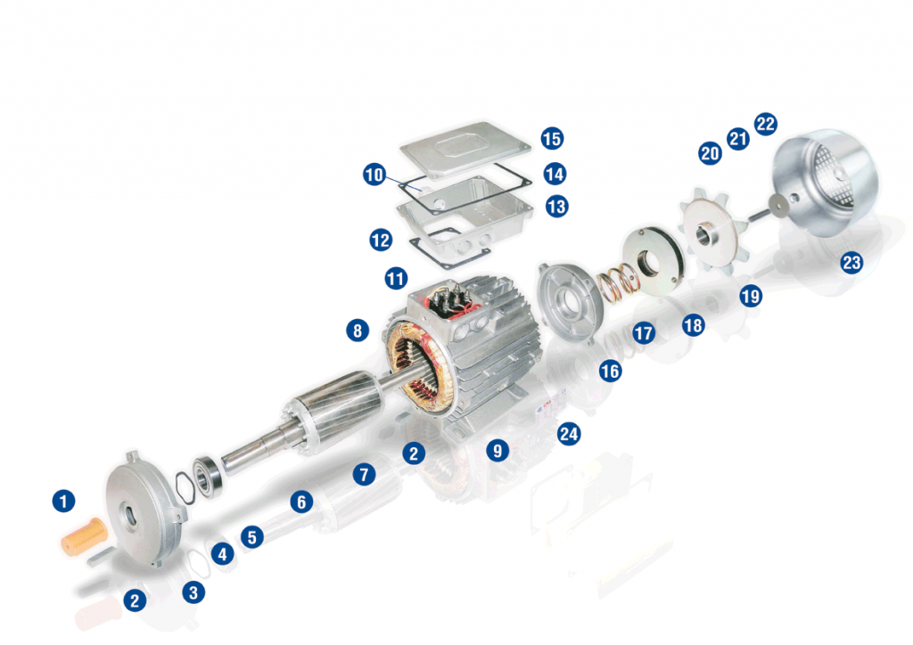
KEY S – DECELERATOR
- 1 – Cover shaft
- 2 – Feather
- 3 – Shield
- 4 – Elastic compensation ring
- 5 – Bearing
- 6 – Drive Shaft
- 7 – Rotor
- 8 – Wound stator
- 9 – Frame
- 10 – Cable inlet
- 11 – Line connection terminal
- 12 – Cover gasket IP55
- 13 – Cover box
- 14 – Gasket IP65
- 15 – Cover box-top
- 16 – Shield brake “S”
- 17 – Spring
- 18 – Magnetic “S” braking assembly
- 19 – Cast iron fan
- 20 – Adjusting screw
- 21 – Washer
- 22 – Self-locking nut
- 23 – Fan cover
- 24 – Motor label plate